Hydraulic oil in mobile equipment reservoirs has disturbances caused by the motion of the equipment. Such designed solutions are baffles.

Why The Tank May Well Be A Hydraulic Fluid S Best Friend
Get Fast Reliable Shipping.
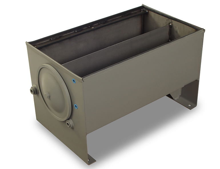
. It features a durable 11 Ga aluminum shell and 12 Ga heads. Standard baffle configuration utilises 3 or 4 equally spaced vertical baffles T12 where T is the internal tank diameter. H L S 15S 15 SUpper baffle Lower baffle Minimum water level Port from previous channel Exit to the sedimentation tank entrance channel.
Suitable for vertical mounting of pump electric motor. In order to reduce oil swirling and improve stability of fluid flow CFD simulations of oil flow inside hydraulic tank were made. Mobile Equipment Reservoir Baffle Innovation.
Hydraulic Tank Baffle Design. Power response and flow response is always carried out in a vessel that has four standard width baffles width 112th of the tank diameter. In this article sloshing is illustrated.
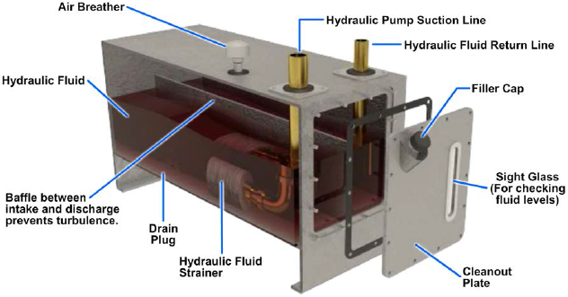
The reservoir should have internal baffles to reduce sloshing and to prevent the hot returning oil from immediately entering the pumps intake port. NPT suction returnports at the bottom of each end of the tank and a 12 in. Request PDF Hydraulic design of baffles in disinfection contact tanks This study focuses on understanding the hydraulic design of baffled contact tanks using computational fluid.
October 20 2014 By Josh Cosford. Company standard which has been around for years states that oil passage cutouts have an area at least 2-12 times the total pump inlet area. H Water depth L Length of the flocculator channel S Space between baffles T Thickness of the baffles B Perpendicular center to center distance between baffles.
Hydraulic Reservoir System Design. The cylinder design and aluminum construction can match your trucks fuel tank for a balanced finished appearance. Reservoirs in industrial applications are spoiled by the extra.
To help cool return fluid it should be. Several variations of new hydraulic tank designs are compared. Rate to determine the distance between baffles the.
Fluid disturbances are commonly called sloshing and cause a number of issues such as breather damage short-circuiting diffusion and entrainment. In the context of the design of a hydraulic tank there are different incentives to design the oil tank as small as possible. The standard baffle design parameters are as follows.
Supplied upainted unless painting is specified larger tanks are fitted with a centre baffle. The total flocculation time is to be 21 min and the water temperature is 15 C. This allows more heat to radiate as it takes a longer route in the tank.
The flocculation basin is to be divided into 3 sections of equal volume each section having constant velocity gradients of 50 35 25 s-1 respectively. Looking for rules of thumb on baffle design for hydraulic tanks. Two rectangular contact tanks were used both of which are assumed to be representative of disinfection tanks for small municipalities throughout the.
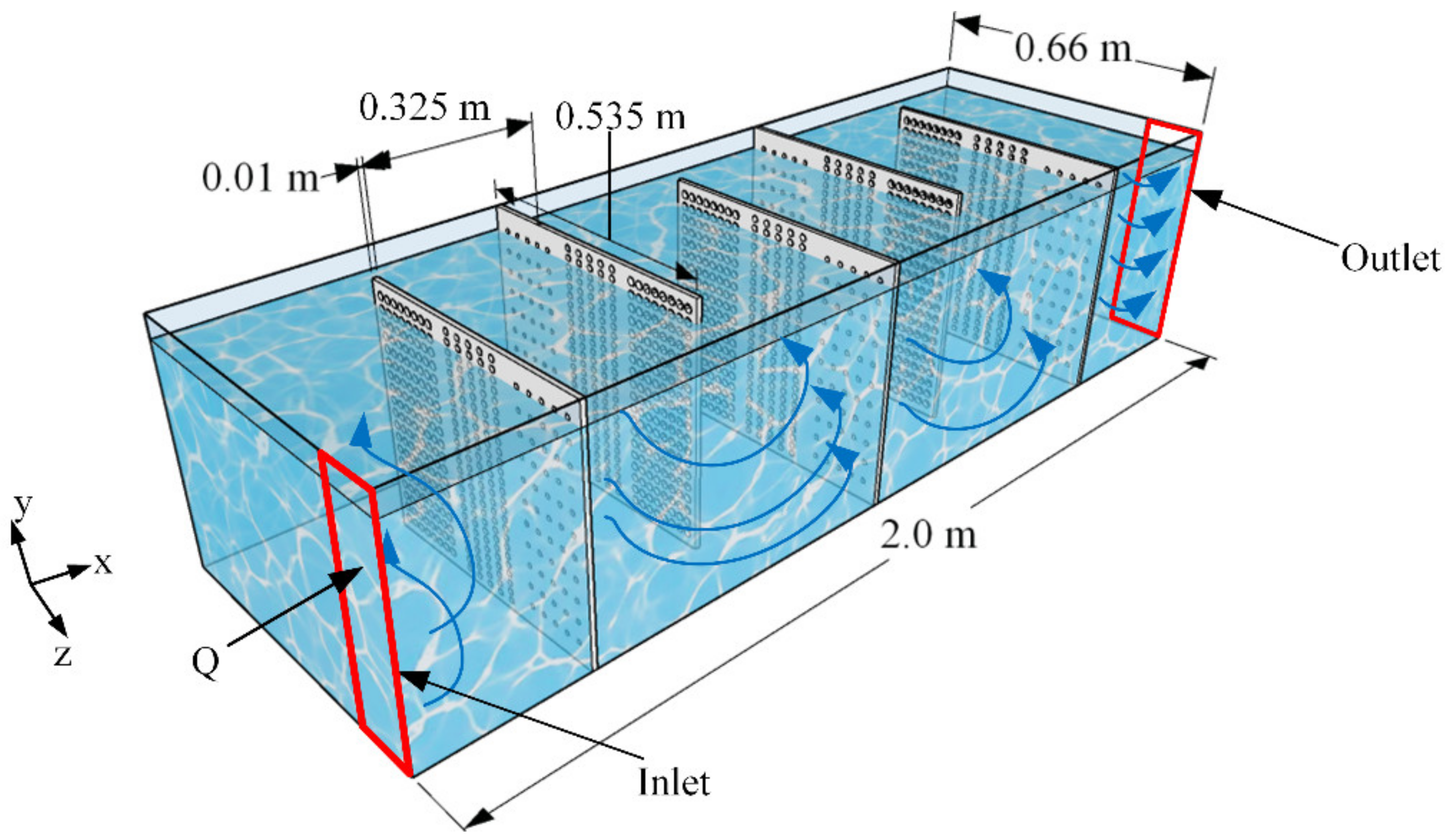
The reservoir includes 2 in. Turbulent flow through the perforated baffle is studied at the perforation hole scale. Ad Search Graingers Online Catalog.
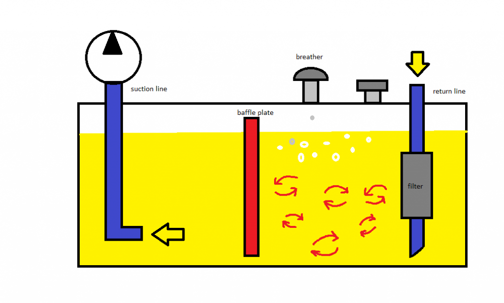
A good hydraulic reservoir should have internal baffles situated in such a way that they prevent return line air from being drawn into the pump inlet. A properly designed reservoir has internal baffles to prevent excessive sloshing of the fluid and to put a partition between the fluid return line and the pump suction line. Through extensive hydraulic fluid analysis Helgesen has developed multiple patented technologies to meet increasing market demand in hydraulic efficiency and performance becoming the global leader in.
H Carlston J Venayagamoorthy S. The default number of baffles is four 4. Baffles and inlets are assessed in depth using both physical tracer studies and computational fluid dynamics CFD simulations.
Baffles direct diffuse and contain fluid and increase tank stiffness Fig. Optimal design parameters for hydraulic vertical flocculation in the package surface water treatment plant. Journal of Hydraulic ResearchDe Recherches.
Steel welded inside outside Unpainted Tanks. The partition forces the returning fluid to travel farther around the tank before. Hydraulic Oil Tanks 10L to 400L Brand.
In this study a perforated baffle design is proposed to improve mixing in contact tanks. The paper presents the development of industrial 400 litre hydraulic tank. Never rework a fuel tank into a hydraulic tank.
NPT portdrain on the tank bottom. Hydraulic System Design Operation. On the one hand a small oil volume results in lower total cost of ownership which gets more.
Hydraulic tank design is often neglected part of the development. Locate the inlet tube under a substantial depth of oil to avoid vortexes or add vanes to the throat of the tube extending outward. Hydraulic design of baffles in disinfection control tanks.
A hydraulic liquid reservoir includes a tank that has a plurality of walls and a baffle structure which divides the inside of the tank into three compartments. An inlet is connected to one lower compartment while an outlet is connected to the second lower compartment and a third upper compartment is interconnected with both the first and second lower compartments at a. Number of Baffles and Baffle Width.
Hydraulic oil spends most of its time in the reservoir and as such various tank design criteria provide benefits for the hydraulic system as a whole. Finished with power coating inside andout Lids. The contribution of jets emerging from the perforations to the mixing process is evaluated in terms of standard mixing indexes for various perforation parameters such as the solidity ratio and hole.
Design a horizontal flow baffled channel flocculatorfor a treatment plant of 10000m 3day capacity. Additionally baffles help the reservoir fluid circulate which promotes heat dissipation from the fluid. A physical barrier baffle that separates fluid entering the reservoir from fluid entering the pump suction line air space above the fluid to accept air that bubbles out of the fluid access to remove used fluid and contaminants from the system and to add new fluid.
Increasing the size or number of baffles beyond this point does little to increase the effectiveness of the mixing. Baffles work to efficiently separate the return flow from the inlet flow. Finished in black steel only Painted Tanks.
When designing the optimum hydraulic reservoir most of the considerations are in keeping the oil clean and cool.

Part 2 Reservoir Hydraulic Power Pack Basic Hydraulic Pneumatic Hindi English Youtube

Industrial Hydraulics Design Hydraulic Reservoir Design
Hydraulic Tank Design And Work Basic Stuffworking Com

Novel Slot Baffle Design To Improve Mixing Efficiency And Reduce Cost Of Disinfection In Drinking Water Treatment Journal Of Environmental Engineering Vol 143 No 9
Reservoirs Strainers Filters And Accumulators Engineering Library
Taking A Deep Dive Into The Hydraulic Reservoir

Hydraulic Reservoirs Fluidsys Training Centre
Water Free Full Text A Perforated Baffle Design To Improve Mixing In Contact Tanks
0 comments
Post a Comment